Want to Improve your Instrument Setup Time?


1. Always use a good heavy duty tripod in good condition (no loose parts).
2. Setup the tripod about chest high over the point.
3. Always use a good wide stance for stability.
4. Always carry the instrument by the carrying handle with one hand under the instrument for support.
5. Attach the instrument to the tripod using the bell housing mount.
6. Using the optical plummet or laser plummet use two legs to place the instrument over the point. Place the toe of your boot near the point to make it easier to find.
7. Firmly plant the tripod feet in the ground using all your weight. Jump up and down on it if you like, you will not break the tripod!
8. Level the instrument by adjusting the tripod legs - don't worry about the optical plummet just yet.
9. Fine adjust the bullseye bubble with the leveling screws.
10. Now, using you optical or laser plummet check the position over the point. Loosen the bell housing and slide the instrument over the point and tighten the bell housing back up (don't over tighten).   The tribrach should not hang over the tripod head at any time.
11. Now level the long bubble or electronic bubble to where it is center in two faces 90 degrees from one another (don't chase your tail).
12. Check your position over the point and make any corrections.
13. Check your level again.
14. Once you have a level instrument and it is over the pint you should be ready to sight in on the backsight and set your zero!


Check out this video for some tips!


Using Weighted Average in TopSURV


You can use the weighted average function in TopSURV if you repeat an observation on a point in topo by using the same point number. I will generally use this feature when setting control with RTK. 

1. Make an observation on your control point. I recommend collecting an average of 30 epochs or more. 

2. After logging your point make a second observation on the same point using the same point number.

3. When prompted select Use as a Check point, Use in weighted average.

If you use more than two observations you can throw out any outliers in the weighted average tab.

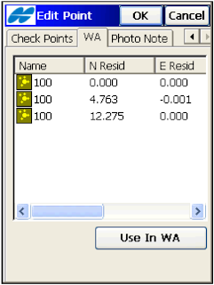
From the TopSURV User Manual: The WA (Weighted Average) tab appears on the Edit Point screen if the point has check points which are used in a weighted average. To exclude a station from a weighted average, highlight the station. Use the Exclude from WA / Use in WA button to exclude / include the highlighted station in averaging.


>See this walk through video 

TopSURV Configurations

Here are a few TopSURV configuration walk throughs for my Military survey friends using the equipment listed below. If you have any questions, comments, or corrections needed drop me a line.

GR-3 Post Processing (Static)

GR-3 Internal Radios (RTK)


GR-3 with TRL-35 (RTK )


GPT-9000 Robotic Configuration (RC-3)

GPT-9000 Conventional/Reflectorless Configuration


DL-101C Auto Level Configurations

Display Background Images in Topcon Tools


The Map and CAD View displays a background image for a work area. Topcon Tools can open only georeferenced image as a background. (Georeferencing of the image establishes the relationship between pixel coordinates and real datum/grid/ground/local coordinates).

If the image is not georeferenced, Topcon Tools can calculate the relationship with the desired coordinate system. To do this, the user has to have the coordinates of the ground control points in the given coordinate system.

I will often use Images from Google Earth to use for my background. In Google Earth I zoom to the desired area for my background and export the image to a JPG format. I will then import and georeference the image in Topcon Tools using the Background Images tools. Remember to do this properly you will need to have coordinates on identifiable points in the image. If you want to create a quick georeferenced image you can get the Lat/Lon coordinates for points in Google Earth and use them create points in Topcon Tools. Convert the Lat/Lon coordinates in Tools to your plane coordinate system (State Plane, UTM,...). This is a nice trick but can be a little drawn out. Hopefully Topcon Tools will soon come up with an automated Google Earth to background image, like AutoCAD, in the future. Below is some detail information from the Topcon Tools user manual, but it is much easier to import an image and georeference than what the manual indicates.   To add a vector or raster image as background to the current job, do the following:

1. Click View > Background images.

2. Click the Add Image button in the Background images dialog box

3. Select the Add Image Button
Select the desired image file in the Open dialog box, and then click Open. This image will be displayed in the left panel (Available Images) of the Background images dialog box. An unlimited number of images can be activated in this panel.

4. Select the needed background image in the left panel and click the double arrows button. This image will display in the right panel (Images used in the jab) of the Background images dialog box. If the coordinate system of the selected image is the same as the job’s coordinate system, this image will be marked with a green icon in the right panel and displayed in the Map and CAD views.
                                                                            
5. Be sure that the Show Background Map entry box is checked (enabled) for the Map/CAD View (To see this check box, right-click on the Map/CAD view, then select Option from the pop-up menu).

View Video Here 


Resources for Finding or Establishing Survey Control


Internet Resources

Most governments will have an agency assigned to maintain a Spatial Reference System to meet economic, social, and environmental needs. Control networks may consist of “hard” monuments that are physical monuments, such as brass caps or chiseled marks on concrete, or “virtual” monuments such as Continuously Operating Reference Stations (CORS). Both will have horizontal or vertical values that reflect the national reference system or vertical datum. Not all nations share the same reference system which can be confusing at times, as there are several kinds of realizations of global geodetic reference systems. Differences among these realizations are caused by slight differences of realized mass centers of the earth, adopted reference ellipsoids and plate motions.

Below are some resources for finding or establishing horizontal or vertical control.

National Geodetic Survey (NGS) - NGS provides the framework for all positioning activities in the Nation. The foundational elements - latitude, longitude, elevation and shoreline information - contribute to informed decision making and impact a wide range of important activities including mapping and charting, flood risk determination, transportation, land use and ecosystem management. NGS' authoritative spatial data, models and tools are vital for the protection and management of natural and manmade resources and support the economic prosperity and environmental health of the Nation. http://www.ngs.noaa.gov/


CORS – NGS manages a network of Continuously Operating Reference Stations (CORS) that provide Global Navigation Satellite System (GNSS) data consisting of carrier phase and code range measurements in support of three dimensional positioning, meteorology, space weather, and geophysical applications throughout the United States, its territories, and a few foreign countries.

Surveyors, GIS users, engineers, scientists, and the public at large that collect GPS data can use CORS data to improve the precision of their positions. CORS enhanced post-processed coordinates approach a few centimeters relative to the National Spatial Reference System, both horizontally and vertically.

The CORS network is a multi-purpose cooperative endeavor involving government, academic, and private organizations. The sites are independently owned and operated. Each agency shares their data with NGS, and NGS in turn analyzes and distributes the data free of charge. As of November 2011, the CORS network contains over 1,800 stations, contributed by over 200 different organizations, and the network continues to expand. http://www.ngs.noaa.gov/CORS/

NGS Data Sheets - Part of the mission of the National Geodetic Survey, is to
provide the public with survey control information, such as Latitude, Longitude, Height and Gravity Data. This is done for publishable stations in the form of DATASHEETS. http://www.ngs.noaa.gov/cgi-bin/datasheet.prl


Online Positioning User Service (OPUS) - OPUS provides simplified access to high-accuracy National Spatial Reference System (NSRS) coordinates. Upload a GPS data file collected with a survey-grade receiver and obtain an NSRS position via email.

OPUS requires minimal user input and uses software which computes coordinates for NGS' Continuously Operating Reference Station (CORS) network. The resulting positions are accurate and consistent with other National Spatial Reference System users.

Your computed NSRS position is sent privately via email, and, if you choose, can also be shared publicly via the NGS website. http://www.ngs.noaa.gov/OPUS/

The NASA Global Differential GPS (GDGPS) System - GDGPS is a complete, highly accurate, and extremely robust real-time GPS monitoring and augmentation system.

Employing a large ground network of real-time reference receivers, innovative network architecture, and award-winning real-time data processing software, the GDGPS System provides decimeter (10 cm) positioning accuracy and sub-nanosecond time transfer accuracy anywhere in the world, on the ground, in the air, and in space, independent of local infrastructure. http://www.gdgps.net/


Automatic Precise Positioning Service (APPS) – APPS offers instant positioning supporting GPS and GLONASS observations. APPS supports file formats in RINEX 2 and RINEX 2.11. Processing Modes include Static and Kinematic. All coordinates are reported in ITRF 2008. http://apps.gdgps.net/apps_file_upload.php


Scripts Orbit and Permanent Array Center (SOPAC) - SOPAC archives high-precision GPS data, particularly for the study of earthquake hazards, tectonic plate motion, crustal deformation, and meteorology. SOPAC calculates and provides precise near real-time and predicted GPS satellite orbits and determines precise polar motion and Earth rotation variations. SOPAC allows users to generate precise coordinates for their input RINEX files using the Scripps Coordinate Update Tool (SCOUT). SOPAC is an International GPS Service (IGS) Global Analysis Center

SCOUT - The Scripps Coordinate Update Tool (SCOUT) can be used to compute mean coordinates of a specific site, by submitting a RINEX file of a particular day. The file may be uncompressed, or in .Z, .gz or .bz compressed format. Both standard observation (o) and hatanaka-compressed (d) files are accepted.

Local Resources

City Engineering Offices – City Engineering offices manage public works projects and construction. The City Enginering office will often have elevation benchmark information and horizontal control networks for the City and local area. Beware though, as City benchmarks may become dated or no longer tied to a known reference datum.

Transportation Departments – Transportation offices can be found at City, County, State and Federal levels. Transportation Departments and are a great resource for transportation maps and related horizontal and vertical control networks. Many offices will have an archive of printed and microfiche plans. Transportation engineering and survey departments will also have topographic maps, aerial imagery, control network information and GIS data.

Water and Utility Departments – Water and utility departments manage the resources and assets that are valuable to the area they serve. Water and Utility departments are a good resource for underground utility and waterline maps. Many have GIS departments that keep maps up to date. Water and utility maps are not usually available via the internet due to security issues.


Airports - Airports can be a valuable resource for vertical control benchmarks. Most have been surveyed to determine a precise elevation for landing air traffic. Benchmarks can often be found at runway ends at public and military airports.

The Geoid and Geoid Models


The Geoid and Geoid Models Review

The geoid is that equipotential surface which would coincide with the mean ocean surface of the Earth, if the oceans and atmosphere were in equilibrium, at rest relative to the rotating Earth, and extended through the continents (such as with very narrow canals). A geoid is the "mathematical figure of the Earth", a smooth but highly irregular surface that corresponds not to the actual surface of the Earth's crust, but to a surface which can only be known through extensive gravitational measurements and calculations.


1=Ocean; 2=Reference ellipsoid; 3=Local plumb line; 4=Continent; 5=Geoid

The gravity field of the earth is neither perfect nor uniform. A flattened ellipsoid is typically used as the idealized earth, but even if the earth were perfectly spherical, the strength of gravity would not be the same everywhere, because density (and therefore mass) varies throughout the planet. This is due to magma distributions, mountain ranges, deep sea trenches, and so on.
If that perfect sphere were then covered in water, the water would not be the same height everywhere. Instead, the water level would be higher or lower depending on the particular strength of gravity in that location.

Source: NGS, Wickipedia

NGS Geoid09

GEOID09 is a refined hybrid model of the geoid in the United States and other territories, which supersedes the previous models GEOID06GEOID03, GEOID99, GEOID96, GEOID93, and GEOID90. This model is intended for converting between the NAD83 ellipsoid reference frame and vertical datum NAVD88, GUVD04 (Guam), ASVD02 (American Samoa), NMVD03(Northern Marianas), PRVD02 (Puerto Rico) and VIVD09 (Virgin Islands).
http://www.ngs.noaa.gov/GEOID/GEOID09/

NGA EGM2008

The official Earth Gravitational Model EGM2008 has been publicly released by the U.S. National Geospatial-Intelligence Agency (NGA) EGM Development Team. This gravitational model is complete to spherical harmonic degree. Full access to the model's coefficients and other descriptive files with additional details about EGM2008 are provided at the NGA website.
Those wishing to use EGM2008 to compute geoid undulation values with respect to WGS 84, may do so using the self-contained suite of coefficient files, FORTRAN software, and pre-computed geoid grids provided on the NGA website.

Create an Area in TopSURV

Use existing points to create an Area

1. Open the edit Area menu.


2. To add an Area, tap ADD in the bottom right corner. Give the Area a name. Using the SELECT PTS pull-down menu select From Map. Select the points in numerical order (or in an order that creates a closed area).

3. Tap CLOSE when finished.

4. Define the Layer states (if needed). Tap CLOSE from the Add Area window to store the Area.

5. Tap CLOSE from the Area menu to complete.
Areas are simple closed lines formed by points.


View the Area in the Map


The map shows points connected into a line and the area that can be filled with the selected style.


Geographic Coordinate Systems


A geographic coordinate system is a coordinate system that enables every location on the Earth to be specified by a set of numbers. The coordinates are often chosen such that one of the numbers represents vertical position, and two or three of the numbers represent horizontal position. A common choice of coordinates is latitude, longitude and elevation.


Below are descriptions of the more common reference frames and coordinate systems.

World Geodetic System of 1984 (WGS 84)

 WGS84 is the reference frame used by the U.S. Department of Defense (DoD) and is defined by the National Geospatial-Intelligence Agency (NGA). WGS 84 is used by DoD for all its mapping, charting, surveying, and navigation needs, including its GPS "broadcast" and "precise" orbits. WGS 84 was defined in January 1987 using Doppler satellite surveying techniques. It was used as the reference frame for broadcast GPS Ephemerides (orbits) beginning January 23, 1987.
This initial version of WGS 84 is now commonly referred to as WGS 84 (Original).
At 0000 GMT January 2, 1994, WGS 84 was upgraded in accuracy using GPS measurements. The formal name then became WGS 84 (G730) since the upgrade date coincided with the start of GPS Week 730. It became the reference frame for broadcast orbits on June 28, 1994. 
On January 20, 2002, the latest realization of WGS 84, called WGS 84 (G1150) was adopted and is the current version. This realization is based on the ITRF 2000. An International Terrestrial Reference Frame (ITRF) is a realization of the International Terrestrial Reference System (ITRS). New ITRF solutions are produced every few years, using the latest mathematical and surveying techniques to attempt to realize the ITRS as precisely as possible. Due to experimental error, any given ITRF will differ very slightly from any other realization of the ITRF. Also, the difference between the latest WGS84 and the latest ITRF is only a few centimeters.

The International Terrestrial Reference System (ITRS)

ITRS is a world spatial reference system co-rotating with the Earth in its diurnal motion in space. The IERS, in charge of providing global references to the astronomical, geodetic and geophysical communities, supervises the realization of the ITRS. Realizations of the ITRS are produced by the IERS ITRS Product Center (ITRS-PC) under the name International Terrestrial Reference Frames (ITRF). ITRF coordinates were obtained by combination of individual TRF solutions computed by IERS analysis centers using the observations of Space Geodesy techniques: GPS , VLBI , SLR, LLR and DORIS. They all use networks of stations located on sites covering the whole Earth.
ITRF2008 is the new realization of the International Terrestrial Reference System. Following the procedure already used for the ITRF2005 formation, the ITRF2008 uses as input data time series of station positions and Earth Orientation Parameters (EOPs) provided by the Technique Centers of the four space geodetic techniques (GPS, VLBI, SLR, DORIS). Based on completely reprocessed solutions of the four techniques, the ITRF2008 is expected to be an improved solution compared to ITF2005.

IGS08 (epoch 2005.00)

Since April 17, 2011, the National Geodetic Survey (NGS) and the other Analysis Centers of the International GNSS Service (IGS) have been providing GPS satellite orbits (ephemerides) that are referred to a new terrestrial reference frame, called IGS08 and defined by the IGS. This new frame is based on GPS observations and was designed to be consistent with the International Terrestrial Reference Frame of 2008 (ITRF). Although, the best fitting Helmert transformation between IGS08 and ITRF2008 for a set of well-established, international GNSS satellite tracking sites is the identity function, the transformed ITRF2008 positions have a site specific "correction" applied to them to create IGS08 positions. Thus the IGS08 position for a particular site may differ from its corresponding ITRF2008 position; however, the velocities remain identical. By using IGS08 coordinates and the associated absolute antenna calibrations in combination with IGS orbits a consistent frame is realized. In addition, NGS has updated the IGS orbits from January 1, 1994 to April 16, 2011 in its online storage with the recently released IGS reprocessed (repro1) orbits that are all aligned consistently with IGS05. For most non-research applications, users can freely mix IGS05 and IGS08 orbits to compute coordinates for control points.

NAD83(2011) epoch 2010.00

NAD 83 (2011) epoch 2010.00 is the current realization of the reference frame fixed to the North American tectonic plate. This realization is used for the vast majority of CORS and NA2011 passive marks, and it includes all stations on, and nearly adjacent to, the North American and Caribbean tectonic plates. These stations are located in the conterminous United States (CONUS), including California, and this realization also includes Alaska, Puerto Rico, and the US Virgin Islands.


The National Imagery and Mapping Agency (NIMA) (formerly the Defense Mapping Agency) adopted a special grid for military use throughout the world called the Universal Transverse Mercator (UTM) grid. In this grid, the world is divided into 60 north-south zones, each covering a strip 6° wide in longitude. These zones are numbered consecutively beginning with Zone 1, between 180° and 174° west longitude, and progressing eastward to Zone 60, between 174° and 180° east longitude. Thus, the conterminous 48 States are covered by 10 zones, from Zone 10 on the west coast through Zone 19 in New England. In each zone, coordinates are measured north and east in meters.

UTM coordinates can be defined with NAD83 or WGS84 realizations.  One should be sure to identify the origins of UTM coordinates before converting to another coordinate system.  A NAD83 realization is typically only used in North America for non-military applications.  


A Word About Metadata

Metadata is data about data. All coordinates files or lists delivered, whether hard copy or in digital medium, should contain metadata indicating the geographic coordinate system, zone, reference frame and its realization (if available), vertical datum (geoid model if applicable), units of measure and the date of the field work.

Creating a Regional Geoid with TopLINK

A geoid file contains data on a physical reference surface. The shape of the geoid reflects the distribution of mass inside the earth. The rise and fall of the surface in a geoid is important for converting GPS-derived ellipsoidal height differences to orthometric height differences.
Global Geoid model files are often too large to store on a data collector so there are various ways to reduce the size of your geoid model to cover a specified area by cutting out a portion of the geoid using boundaries or a radial area.


Using Topcon Link, you can create a Topcon geoid file (*.gff) for a defined area from any supported geoid model creating a sub-section of the selected geoid file by identifying the minimum and maximum longitude and latitude. This smaller file can then be exported into TopSURV.  When converting from a Geoid file, the user can enable and select only the Change geoid bounds option.


Processing Static Files with OPUS


The Online Positioning User Service (OPUS) provides simplified access to high-accuracy National Spatial Reference System (NSRS) coordinates. Upload a GPS data file collected with a survey-grade receiver and obtain an NSRS position via email.
For Static Data Collection Reference: Collecting Static Data with the Topcon GRS-1
For Downloading TPS Log Files Reference: Downloading Topcon Static Files With TRU
OPUS requires minimal user input and uses software which computes coordinates for NGS' Continuously Operating Reference Station (CORS) network. The resulting positions are accurate and consistent with other National Spatial Reference System users.
Your computed NSRS position is sent privately via email, and, if you choose, can also be shared publicly via the NGS website. To use properly, please familiarize yourself with the information below.

Uploading

Using OPUS requires just five simple steps:


1. EMAIL
Enter the email address (e.g., your.email@domain.com) where you want OPUS to send your solution report.

image

2. DATA FILE
Provide OPUS a GPS observables data file in any format (for automatic conversion to RINEX format by UNAVCO's teqc converter) or convert it to RINEX yourself first. OPUS also recognizes compressed (UNIX or Hatanaka.yyd) or zipped (gzip or pkzip) files, including multiple data files in a single zip archive. For Topcon users the raw TPS file is accepted.


image

OPUS accepts receiver epoch rates of 1,2,3,5,10,15 or 30 seconds, all of which are decimated to 30 seconds for processing. Note: Though your data file may already contain survey metadata, including antenna type, height, and mark information; these are IGNORED as NGS has found they are inconsistently formatted.


3. ANTENNA TYPE
Select the antenna brand and model you used. This allows OPUS to determine the appropriate antenna calibration model for processing. Take care! Selection of an incorrect or default antenna may result in a height error as large as 10 cm. See Topcon antenna calibration to help find an exact match.


image


4. ANTENNA HEIGHT
Enter the vertical height in meters of your Antenna Reference Point (ARP) above the mark you are positioning, as shown in the image below. The ARP for your antenna type, usually the center of the base or tripod mount, is illustrated at Topcon antenna calibration. If you enter a 0.0 antenna height, OPUS will return the position of your ARP.


imageimage


5. OPTIONS
Press OPTIONS to customize the way your solution is performed and/or reported. Your selections will override the optimized OPUS defaults and should therefore only be employed by experienced users.

PROCESSOR

OPUS currently provides two distinct processing softwares optimized for different data types:
  1. STATIC (Best Solution): For OPUS static processing, your data file must contain at least 2 hours but not more than 48 hours of data.
  2. RAPID-STATIC: For OPUS rapid-static processing, your data file must contain at least 15 minutes but not more than 2 hours of data, with all four observation types (L1,L2, P1 (or C1), and P2) present at each epoch used.

Downloading Static Files with TRU


After completing a static survey you will need to download data files to a computer for storage, post-processing or backup. Also, the receiver memory holds a finite amount of files and information, so downloading data prevents files from being lost. The new Topcon Receiver Utility (TRU) can be used to download files from the receiver to your computer, and to delete files from the receiver using a serial or Bluetooth connection.
Connecting the Receiver and a Computer
Make sure the computer has TRU installed. A current version of TRU can be found at www.topconpositioning.com on the user secure site.

Topcon Receiver Utility (TRU) is Topcon's hardware configuration software available for installation on desktop computers and hand-held controllers.
TRU is primarily designed for advanced users who need to configure their receiver hardware, or peripheral devices (internal and external modems, Bluetooth boards, etc.).
The application currently has two modes, Terminal and Receiver Managing, which include the following functionality:
  • Receiver Information Dialogue
  • GNSS Receiver Authorization Options Management
  • Upload of Option Authorization Files (OAF) to a Topcon GNSS receiver
  • Upload / update of component Firmware (such as Power Board, GNSS Receiver Board, internal Bluetooth, Radios, and / or Modems)
  • Sending of utility commands such as Clear NVRAM or Reset Receiver
Before you can download files, you must connect your receiver and computer.
...Using Bluetooth
Perform the following to download files using Bluetooth:
1. Power on Topcon GPS Receiver and PC with Bluetooth enabled. (pairing is not required)
2. Launch TRU.

image

3. Set the Application Mode to Receiver Managing

image

4. From the Device pull-down Menu select Connect.

image

5. Select Bluetooth for the connection setting.
6. Click on the image button next to Device Name to search for the Receiver Bluetooth port.

image
7. Select the receiver port and click image

image

8. Click Connect.

imageimage


9. Click on File Explorer image

10. To down right-click on the log file in the File tab and select Download.

image

11. Browse to the directory on your PC where you want to save the TPS file and click 
image

12. Delete files on the receiver by right-clicking and selecting Delete.

image

13. Disconnect from the device upon completion of downloads and file maintenance and Exit TRU.

imageimage